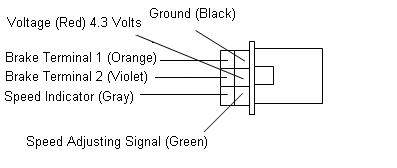
Controller Ct 302s9 Wiring Diagram
LT10 fuel only 4 cyl. In this article we are sharing the basic concepts of PLC and DCS control systems Wiring Diagrams for Digital Input DI Digital Output DO Analog Input AI and Analog Output AO signals.
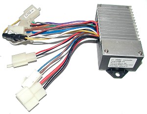
Tnc Scooters Ct 302s9 Product Specification
X2 CONTROLLER WIRING DIAGRAM Water main Master valve Optional Water to zones Solenoid valves X2 controller Power 120 VAC transformer Additional valves Irrigation wire 18 AWG Common wire Station wires Use sheathed direct-burial irrigation wire.
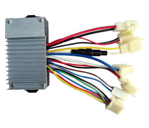
Controller ct 302s9 wiring diagram. Honda ct70 st70 st50 1969 1982 workshop manual wiring diagram for honda trail 70 carcareautorepair com 1982 ct70 wiring diagram zeebba com honda ct70 lifan amp clone engine 12 volt wiring diagram 1982 ct70 wiring diagram roshdmag org honda ct 70 wiring diagrams honda ct70 mini bike photos epub download 1982 honda ct70 wiring diagram ebook download. Found on newer versions of CT-302S9 controller. CT-302S9 24V 350W Electric Scooter Speed Controller Designed for 24 Volt motors up to 350 Watts.
Up to 16 inputs per controller Connect Earth Terminal to Cold Water Pipe Connect to RS-232 PC port if 6-pin modular jack is not used. Opposite end of the romex lead. Two types of CT are manufactured.
The new freeze control plugs into that two lead plug. Wiring Yiyun LB27 24V is similar to Yiyun YK31C 36V from the same manufacturer. Wiring Diagrams 55-57 Type S AC Combination Magnetic Starters58-59 Class 8538 and 8539 58-59 3-Phase Size 0-5 58.
The advantage of this general-purpose controller is that is can be used with a wide range of operating voltages from approximately 5 V to 18 V. Do not remove factory-installed jumpers between Z3 Z4 and Z5 unless ZSI is connected. 1Ø WIRING DIAGRAM Diagram ER4 1Ø WIRING DIAGRAMS M 1 LNE 3 active wires plus auto-reset thermal contacts Codes.
LT10 Ford 6 cyl standard. Construction and Types of Current Transformers. Under Voltage protection 20.
Wiring Diagrams for MasterPact NW Circuit Breakers. Terminal Block Installation Guide. 239 694 0089 - Fax.
Power Indicator Connector Plug. LT10 fuel only 6 cyl. Overcurrent Protection for 3-Wire Control Circuits 11 AC Manual Starters and Manual Motor Starting Switches 12 Class 2510 12 Class 2511 and 2512 13 2-Speed AC Manual Starters and.
CT wiring diagram. All diagrams show circuit breaker open connected and charged. Use waterproof connectors for all wire splices.
Stepper Motor Controller Schematic Circuit Diagram. Other fans as shown Brown Black Blue M 1 GreenY ellow Brown Cap Black CE31 only Single phase AC motor with capacitor Blue or Grey A N SILDES These diagrams mainly apply to EXTERNAL ROTOR MOTORSbut some standard. Maximum current 25 Amps.
LT10 60-2 4 cyl. Please consult your dealer for details. Under Voltage protection 205 Volts.
Safety meet code peace of mind circuits current- Purpose. On line straight-through CT Figure 6 bar primary type and wound primary type. Things to Consider Before You Start- Power What type of power is going to be provided.
Do not remove factory-installed jumper between T1 and T2 unless neutral CT is connected. Electronic Control Kit Wiring Diagrams. 0 203 3 minutes read.
Notes Refer to the Signature loop controller installation sheet for SLC wiring. CT Current Transformer Wiring connections for commercial Form 9S electric meter installation. Wiring Diagrams of PLC and DCS Systems DI DO AI AO.
Showing wiring from a current transformer in a cabinet to th. Connections are correct as per wiring diagram otherwise problems will result with the REGISTER DISPLAYS For HEALTH SAFETY reasons it should be noted that if a current transformer is operated with the secondary S1 and S2 open circuited DANGEROUS VOLTAGES may be generated at the secondary terminals or leads. Verify that all field wiring is free of opens shorts and ground faults.
But this controller is smaller and has fewer terminals. Charger Connector Connector Plug. Diagram installer meter responsibility wiring wiring diagram.
About 6 mm from the ends of all wires that connect to the terminal block of the module. To install the Terminal Blocks for these panelized lighting modules. Stepper motors are available in several versions and sizes with a variety of operating voltages.
LT10 fuel only 8 cyl. Make all wiring connections as shown in Figure 2. Refer to the Control4 Terminal Block wiring diagrams in this guide along with the.
3Ø WIRING DIAGRAMS 1Ø WIRING DIAGRAMS Diagram ER9 M 3 1 5 9 3 7 11 Low Speed High Speed U1 V1 W1 W2 U2 V2 TK TK Thermal Overloads TWO SPEED STARDELTA MOTOR Switch M 3 0-10V 20V 415V AC 4-20mA Outp uts Diagram IC2 M 1 240V AC 0-10V Outp ut Diagram IC3 M 1 0-10V 4-20mA 240V AC Outp uts These diagrams are current at the time of publication. Wise Tech July 19 2019. Lock Connector Connector Plug.
Replaces Six Wire Connector. 8-Port Ethernet Switch 8-Channel Dimmer and. Ring type doughnut CT Figure 7 Ring type CT is constructed of an iron toroid which forms the core of the transformer and is wound with secondary turns.
CT-V900-A 2-Door Controller Keypad 2 Keypad 1 To PC RS-232 Port using DB-9F Reader and keypad wiring may differ from diagram. To wire the module. Do not install jumper between T3 and T4.
Maximum current 30 Amps. LT10 Honda 4 cyl standard. Speed Controller SPD-CT302S9 Installation and Wiring.
For wire length over 24 ft consult the National Electrical Code for proper sizingDo you have a wiring diagram for a dometic thermostat - Answered by a verified RV Mechanic See the wiring diagram inside the lid. LT-9c LT-10 use the same wiring diagrams. LB27 is good controller for for easier load or example an electric scootera quad bike for children different drives where is used the brush motor.
Currie 24V 500W-600W Electric Scooter Speed Controller with 3-Wire Throttle Connector Designed for 24 Volt motors up to 600 Watts. Current Transformer Wiring Diagram REV 33 M CRO ONTROL SYSTEMS SHIELD DRAIN WIRED TO EARTH GROUND Sl GND SHIELDED CABLE MicR0 CONTROL SYSTEMS Sl GND 5 DIGITAL ANALOG 5580 Enterprise Pkwy Fort Myers FL 33905 USA Phone.
Tnc Scooters Ct 302s9 Product Specification
Spd Ct302s9 Installation And Wiring


